
How we analyze a structure tends to have an effect on how it is designed for compliance to the steel or concrete code.
Now, most codes advise or even sometimes mandate accounting for second-order effects in the structure by performing a second-order analysis.
What is second-order analysis ?
Nope!
Let's start with the question "What is a first-order analysis?"
Answer: During the course of this analysis, one basically assumes that the structure has a small deflection behavior. Loads applied as load cases in the software are effectively applied on the "undeformed" structure, with the deflections generated for each such load cases, algebraically added to compute combined effects. Thus deflections have no bearing on the magnitude of the design effects and are essentially decoupled.
Is it a valid assumption though?
Let's just imagine a simple platform supporting industrial operations in the ambient environment. Such a platform might support heavy vertical loads from the equipment/goods as well as workers. At the same time, wind load shall act on the structural as well as other supported elements of the structure, causing the frame to deflect, with the vertical loads still acting on the structure, albeit at an additional eccentricity (w.r.t supports) as compared to before.
Also, vertical loads (read compressive loads) would tend to 'soften' the vertical elements in this case, affecting the stiffness of such elements. This might make the load-deflection behavior become non-linear.
Vertical Loads acting in unison with Lateral Loads
This is not quite captured in a first-order analysis and this is where the second-order analysis comes into the picture.
Second Order Analysis is the method that helps to capture two important effects:
The forces and moments computed take full account of the effects due to the deformed shape of both the structure and its members and where the equilibrium is satisfied on the deformed geometry of the structure.
The effect, which axial loads have on structure stiffness, which is also sometimes called "Stress Stiffening". Tensile loads tend to stiffen the structure (by trying to straighten the elements) while compressive loads tend to reduce the stiffness by accentuating deformation.
The slender the structure, severe shall be the above two mentioned effects, hence if not addressed could lead to an under-estimation of design forces.
Second-Order Analysis requires significant computation prowess and hence was not the go-to method before the advent of powerful software capable of handling large mathematical information. Then, how were these effects accounted for?
Accounting for second-order effects after a first-order analysis
As the analysis, doesn't account for the coupling between forces and deflections, it became imperative to account for them at the 'post-processing' stage. And this method is termed as the 'moment amplification method'.
Section 4.4.2 & Appendix F of AS4100 address the requirements for this quite succinctly. But one also has to pay attention to the limitations of this 'magnification' process for high values of deflections & axial forces, with the code recommending to revert to the second-order analysis in such cases.
One thing to note is that both methods assume elastic properties of the material being used.
Thus, AS4100 recommends two types of elastic analysis. Section 4.4 states that the engineer can employ one of the two types of analysis methods mentioned below:
First Order Linear Elastic Method and account for second-order effects as a 'post-process' step.
Second Order Linear Elastic Method, which directly captures the secondary effects in the analysis stage itself.
Appendix E of AS4100 throws a bit more light on the second-order elastic analysis as well. It would help to know that it is also sometimes referred to as kinematic or geometric non-linearity.
But how do software like SAP2000 account for second-order effects?
SAP2000 calls the effect of loads acting on the deformed geometry of the structure as P-Delta effect and states that the P-Delta effects come from two sources
Global Translation of the frame (P-Δ): caused due to overall sway of the structure.
Local Deformation of members within the frame (P-δ): caused due to deformation of member between ends and significant in slender columns or columns bent in single curvature.
But Richard Dobson in an article (link provided below) states that the P-Delta (both small and large) effect is actually one of the many second-order effects. We are trying to dive a bit more into literature to find basis for this statement, which we shall try to cover in another blog.
P-Δ effect

This effect is due to the relative lateral movement of the member ends from sway action.
Note: SAP2000 considers only the transverse deflection in the deformed configuration. Change in the moment due to change in length of ember is neglected by the software.
P-δ effect

This effect is due to the interaction of individual member curvature (from bending moments) with the axial compression forces present. For this effect to manifest, there need not be any relative transverse displacement between member ends.
We won't go much in detail about these effects, as enough literature explaining them is already available online.
The textbook we would recommend for understanding these effects in conjunction with AS4100 is the 'Steel Designer's Handbook' by Branko Gorenc, Ron Tinyou & Arun Syam.
Online Resources/Literature
Skyciv an online structural analysis and design software package explains P-Δ: https://skyciv.com/education/p-delta-analysis-and-p-delta-effects/
RISA: https://risa.com/risahelp/risa3d/Content/3D_2D_Only_Topics/P-Little%20Delta%20-%20Analysis.htm
An article by Richard Dobson discusses the second-order effects: http://www.newsteelconstruction.com/wp/wp-content/uploads/TechPaper/NSCJan03_P-Delta.pdf
CSI Video Tutorial: https://www.youtube.com/watch?v=YzWocAtK03I
CSI Analysis Reference Manual: Chapter 22-Geometric Nonlinearity
Most of the software capture P-Δ with ease, though it seems that P-δ might cause them a bit of a 'heart burn'. Its only when the members are broken into multiple elements (those subjected to compressive loads) that the small δ is effectively captured. SAP2000 strongly advises avoiding breaking members manually as they may mess with the computation of various design factors.
Solution for better capturing P-δ in SAP2000
The way around is to give a maximum mesh size for those elements which are subjected to considerable axial loads (e.g. columns, but not limited to), so that internal elements within a member are created only during the run time. We did try to arrive at an optimum mesh size but found that every problem was giving a different solution based on changes in load, geometry etc. Hence the user is advised to run a few iterations and observe the changes in member forces. Where the internal forces cease to change too much, inspite of change in the mesh size, that should be the optimum mesh size. SAP2000 manual recommends dividing the structural member into two or more frame elements.
We got in touch with the CSI tech team to ascertain the accuracy of this methodology and this is what they said, "It is NOT necessary to divide or mesh frame elements to capture small P-delta, although the accuracy can be improved by doing so. The frame element inherently captures small P-delta effects by assuming a cubic-shape curve. This is reasonably accurate for members with an effective length factor of 1.0 or larger, provided you are not too close to the buckling load."
CAUTION!
Do not mesh all the members of the model as it would cause a significant increase in computation time. We generally avoid meshing secondary beams, plan and elevation bracings, primary beams subjected to only flexural forces, as it helps in reducing computation time.

Menu to assign maximum mesh size to frame elements
There are two ways to perform a P-delta analysis in SAP2000 as shown in the video tutorial (link provided in Resources). We have adopted the method to create non-linear cases representing load combinations combining vertical and lateral load cases.

Using a non-linear load case definition to define load combinations that combine vertical loads and lateral loads
As seen above, the software gives two options for P-Delta:
P-Delta
P-Delta plus Large Dispalcements
P-Delta essentially captures stress effects and is hence also known as large-stress effect in CSI parlance and is useful for considering the effect of gravity loads upon the lateral stiffness of the building. Tensile forces tend to resist the rotation of elements and stiffen the structure while compressive forces tend to enhance the rotation of elements and destabilize the structure. Thus one can expect some coupling between loads and displacements/rotations, although the manual specifically mentions that only a 'partial' account of the deformed configuration of the structure.
Large Displacements All equilibrium equations are written in the deformed configuration of the structure capturing large displacements and rotations (but assuming the strains to be small) and generally require large iterations. This means that if the position or orientation of an element changes, its effect upon the structure is accounted for. However, if the element changes significantly in shape or size, this effect is ignored. This option should be used for any structures undergoing significant deformations.
A discussion thread on the Autodesk forum is dedicated to understanding the difference between P-Delta and P-Delta plus large displacements: https://forums.autodesk.com/t5/robot-structural-analysis-forum/p-delta-vs-large-displacement/td-p/8953909
We are of the opinion that in order to achieve compliance to AS4100 second-order analysis requirements, the P-Delta +Large Displacements option should be used ideally in structures undergoing large deformations (e.g. structures with cables), while p-Delta should be enough for normal industrial structures. Whatever the chosen choice we often re-run the analysis for both sets, to understand the variation in results and also check the accuracy of the results obtained. Comparing the results with a conventional first-order analysis is also a good idea and gives information about the impact of deformation on the stability & strength of a structure.
Sample Problem

A parametric portal frame was created in Grasshopper with two load cases accounting for Vertical and lateral loads.
Vertical Load is a UDL of 25kN/m
Lateral Load is a Lateral nodal load of 25kN
Three sets of load combinations have been created to account for
First order analysis
P-Delta Analysis
Pdelta plus Large Displacement Analysis
The vertical members have been meshed to a maximum size of 200mm (well we do have decent hardware configuration to give SAP2000 all it wants, hence choosing a fine mesh), but do remember that a division of a member into 2 or more elements generally suffices SAP2000 requirements.
The profiles and materials used are typical configurations adopted in the land down under (Australia).
The supports have been pinned, to make the model susceptible to lateral loads.
Note: The model has been generated with a view to understanding various analyses options offered by SAP2000 and does not represent real-time engineering problem/information.
One needs to have the following software/plugins to play around with the Grasshopper file.
GH SAP2000 plugin provided by Geometry Gym

GH Script
Results

Results generated for a 6.5m long and 9m high portal frame
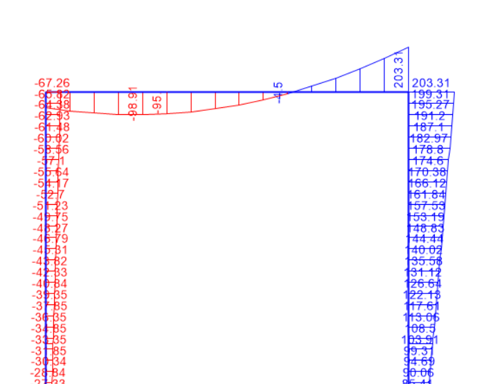
Bending Moment @ column top for SO-PDelta

Deflection plot (SO-PDelta)
Thus, P-Delta computes higher deflections and forces/moments as viz-a-viz the first order analysis, which impresses upon us the need to go for second order analysis.
We shall discuss more about the impact of various analyses options on the steel design procedure in another blog.
GH File Download.
If you have any queries/comments please drop a mail to contact@tectumechanics.com.
TM-BL-AN-001
Comments